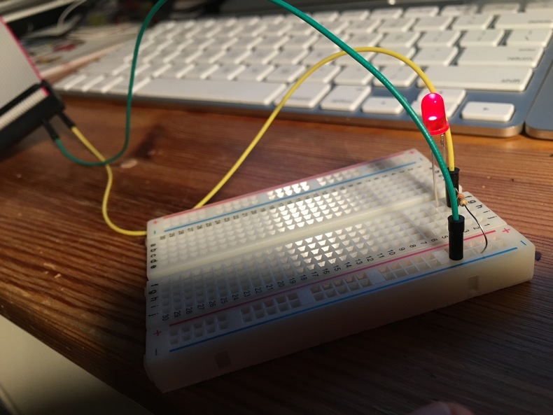
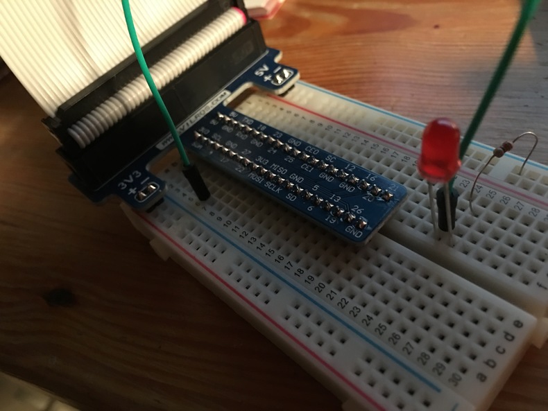
Yesterday I took the day off from raspberry pi and decorated our Christmas tree. Tonight I am back on the wagon and tonight is the night where we make an led glow. The first process is to lean what is this gpio thing about. Ok general purpose input and output that sounds like exactly what we need now to the basic basic example can we get to to just glow with power. I found a simple guide and put together an LED and a small resistor.
it glows
#Pieces
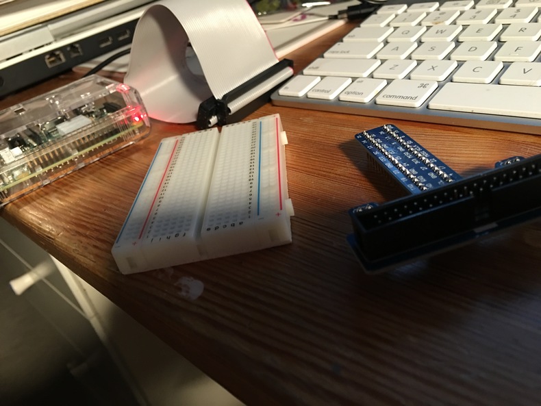 Now that we have that accomplished let’s see what pieces we have to play with in our box. My first idea was what in the heck is this thing and how does it work? Turns out it is a breakout board
#Together
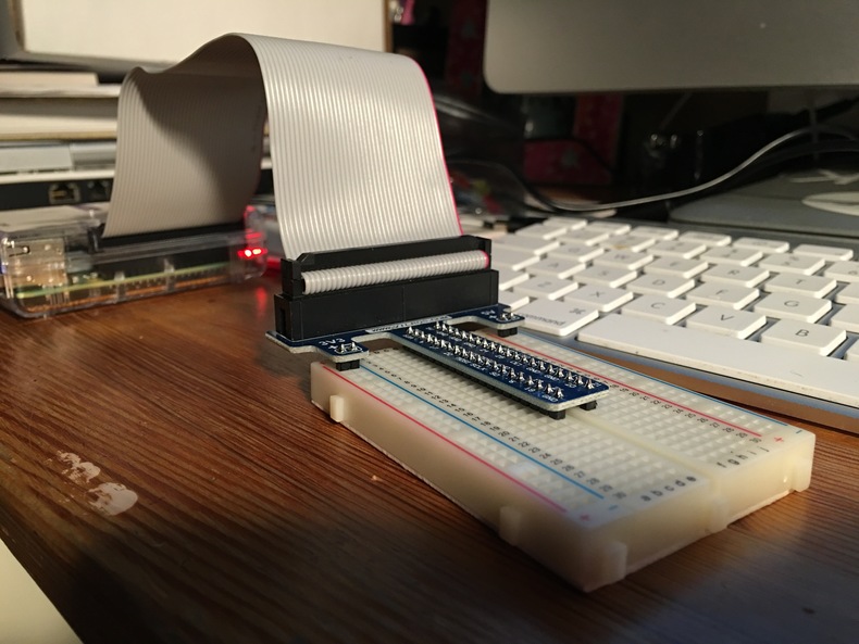
Now that I know what this thing is let’s get it together.
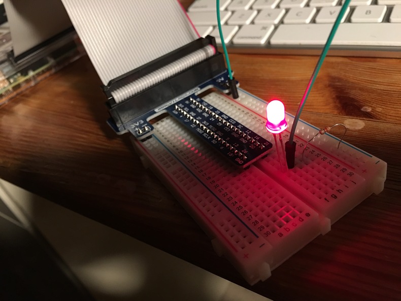
 Before we go forward can we get it to light up again? And yes we can.
#Moving To Pin 17 (GPIO0)
Now we can move to a user controlled pin and let’s go to pin 17 which I learned was 0 based from this pin diagram.
Since we have the breakout board hooked to the breadboard we can easily move the wire to the new home.
So next up is how do we turn this pin on? Based on the first guide we can use the
gpio utility
If we run the following commands we have succes.
gpio mode 0 out
gpio write 0 1
gpio write 0 0
#Results
Mental Dump
- No idea what i am doing, but was able to do something.
- Learned about the ribbon cable breakout to breadboard
- Created a circuit, need to read up why the resistor is required.
- Used
gpioto turn on a pin and thus illuminate an LED.